Used DRL-344 Controlled Automation Drill Line In StockLength Measuring Options
No longer available
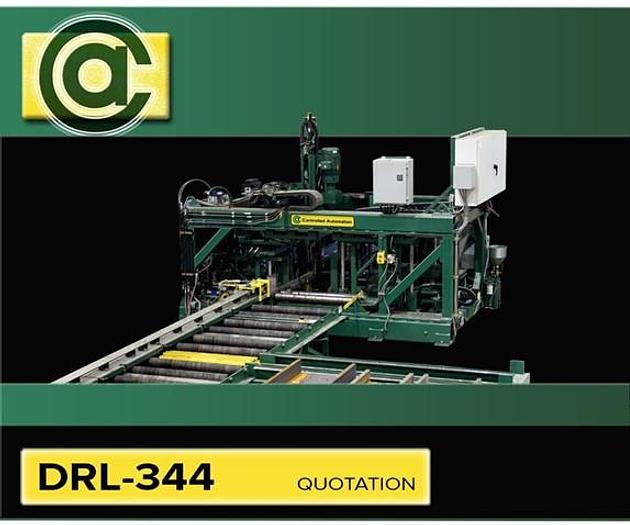
Used DRL-344 Controlled Automation Drill Line In StockLength Measuring Options
$299,990 (USD)
Location:Little Rock, AR
Description
The base structure of the drill is made from a framework of structural steel tubing. This frame was designed from the ground up to provide a structure rigid enough to run high speed carbide tooling.
Each drill spindle has the ability to move approximately 24” (609mm) down the length of the material. When the material stops, all holes within this window can be drilled without moving the material again. This allows for highly accurate holes and for lower total drilling times per structural section.
The tool feeding system uses a closed loop servo control through a precision ball screw assembly. Velocity, torque, and position are all controlled at a 1 KHz sample rate for each axis. During the feeding cycle the tool location is constantly monitored and updated by a series of complex algorithms sampling torque and change in position. This ensures that the tool is always drilling material and the tool is always protected. The entire drill spindle is moved in a block-style arrangement supported by precision preloaded linear guides and bearings. This helps with rigidity and accuracy of the tool as well as giving maximum usable horsepower at the tool.
The spindle rotation is produced by an AC Inverter Drive and matched motor drive through a 3:1 reduction. This allows the rpm to remain constant during feeding of the tool. This also helps achieve precise chip load when combined with the spindle feeding system. Keeping a steady chip load preserves the life of the tooling.
Real Time Tool Feed Adjustment
At anytime while the machine is running the drilling parameters can be fine tuned from the drill bit data table settings. This user screen can also be used to turn on coolant, activate peck feed, or just to monitor drilling thrust.
The drill has powered pinch wheels on the in-feed and the out-feed conveyors of the machine that work in unison to pull the material through the machine but may be operated independently by the operator when needed. The pinch wheels keep the material tightly held throughout the processing of the holes. The pinch wheels are also geared to solid conveyor rolls which assist in pulling the material through the machine and support the material on the horizontal datum line. These solid rolls are further chained to the conveyors to give even more surface area to assist in accelerating the material during length positioning. Since the conveyors help power the material through the machine, the DRL-344 can be installed in your shop without a special foundation.
The pushed probe is mounted on the out-feed side of the machine and the material pushes the probe as the material is processed. This option works well with a tandem saw configuration with the saw located on the in-feed side of the machine. This configuration allows the material to be transferred onto the in-feed conveyor from either side. The material can only be transferred off the out-feed conveyor on the non- probe carriage side.
The following probe is mounted on the in-feed side of the machine and rides against the trailing end of the material as the material is being processed through the machine. An electric eye senses the leading end of the material as the material enters the machine. This option works exceptionally well with a tandem saw configuration with the saw located on the out-feed of the machine. This configuration allows the material to be transferred to either side of the out-feed conveyor. The material can only be transferred onto the in-feed conveyor from the non-probe carriage side. Both the pushed probe and the following probe use a measuring carriage with a cable festooning system. A measuring rack and matched pinion turn a counting device as the carriage is moved. The rack is mounted to the carriage guide bar and the carriage guide bar is mounted to the conveyor. The measuring rack is calibrated to the machine during on site installation to ensure accuracy. The measuring probe carriage provides an accurate, repeatable, and predictable method for the length measurement of the material.
Controlled Automation can supply the drill with a dual wheel measuring system. This system uses two measuring wheels (one in-feed and one out-feed) that ride against the material and turn counting devices as the material moves. The measuring wheels are calibrated during on-site installation of the machine. This system can be used with any transfer conveyor configuration. The measuring wheel is not as repeatable or predictable as the measuring probe carriage type. A debris brush cleans the material as it enters the measuring wheels to help minimize inaccuracies. The wheel measuring software allows the operator to measure the length position of a layout mark placed on the material at the operator’s discretion, and then enter the layout marks “true length position” back into the controller to correct any wheel measuring inaccuracies during a part run.
The material clamps hold the material tight against the vertical and horizontal datum planes during high speed drilling to minimize vibration, maintain hole accuracy, and help preserve tool life. The material clamps completely release the material when the material is positioned in length but remain clamped when the drill spindles move in length from hole to hole. This way the spindles spend more time drilling and not waiting for material to be positioned and clamped.
SPECIFICATIONS AND CONDITION ARE CORRECT TO THE BEST OF OUR KNOWLEDGE AND ARE SUBJECT TO YOUR VERIFICATION AND CORRECTION. THE CONDITION OF THE MACHINE IS AS IT HAS BEEN REPRESENTED TO US. ALL MACHINES ARE SUBJECT TO PRIOR SALE. EVERY MACHINE, UNLESS OTHERWISE SPECIFIED, IS OFFERED SUBJECT TO OUR GUARANTEE THAT IF FOUND TO BE MECHANICALLY UNSATISFACTORY WITHIN 30 DAYS AFTER SHIPMENT, SAME MY BE RETURNED, FREIGHT PREPAID FOR FULL CREDIT OR REPAIRED AT DEALER’S OPTION. ALL MACHINES RETURNED TO US MUST BE IN AS GOOD A CONDITION AS WHEN SHIPPED.
Specifications
| Condition | Used |
| .............................maximum material lbs/ft | 1000lbs. |
| ............................maximum material thickness | 6" |
| ..........................maximum material height | 18” (457mm) |
| ..........................maximum material width | 44” (1.1m) |
| ..........................minimum material height | 3/4” (18mm) |
| ..........................minimum material width | 4” (101mm) |
| ..........................minimum material length | 9’ (2.7m) |
| ..........................minimum angle size | 4” x 3” x ¼” (101mm x 76mm x 6mm) short leg vertical |
| ...........................material types | W, HP, C, MC, L, HSS (tubing), PL, FB |