New CA Wheel Blast Machine
No longer available
New CA Wheel Blast Machine
Location:Little Rock, AR
Description
Terms
30% with order
65% prior to shipping
5% within 30 days after successful start-up
Warranty
12 months
Controlled Automation (SciTeex) will repair or replace any defective parts due to material or workmanship for a period of 12 months after the completion of the start-up. Controlled Automation (SciTeex) will pay for all travel and expenses for this 12 month period. All parts are warranted for one year after installation. Machine warranty begins after installation but no longer than 60 days after shipment, whichever date comes first.
Shipping of parts is excluded after the first 120 days. If a failure is caused by abuse, neglect, or damage by the Customer, the Customer will need to pay for all parts and all expenses incurred by Controlled Automation. The warranty does not include normal wear items such as abrasives, turbine wearable parts, tooling, filters, consumables, etc….
All other extended warranties by other component manufacturers are transferred to the Customer.
Installation & Training
Included
Power Requirements
Standard Power Voltage is 460 volts 3-phase at 60 Hz. Customer must specify when a different voltage is required.
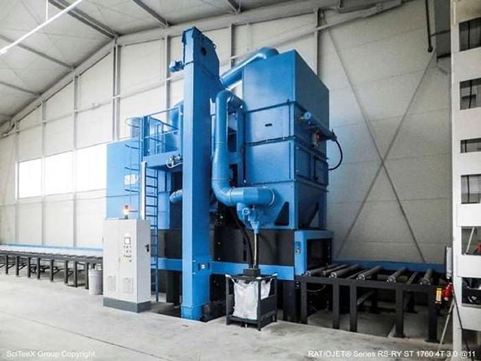
MACHINE CONSTRUCTION
The machine consists of the following elements: entrance vestibule, blast cabinet, exit vestibule.
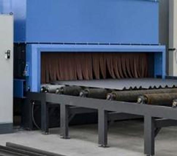
Entrance Vestibule
The entrance vestibule is the first section of the machine and it is constructed with several layers of abrasion resistant rubber curtains to prevent abrasive escaping from the machine. These curtains also isolate the blast cabinet dust and noise emission. The entrance vestibule is
under-pressure and ventilated by the dust collector
Blast Cabinet
The blast cabinet is a welded construction made of 5/16” thick manganese steel and additionally lined inside with protective HARDOX and manganese steel plates of thickness from 5/32” to 5/16”. The side wall of the cabinet area is constructed with a service access door complete with a limit switch.
Internally, all the blast cabinet walls are made of 2 layers of abrasive resistant steel, this exceptional structure contributes to the long service life of the machine.
The lower section of the machine is fabricated to form a hopper within which the abrasive return screw conveyor is installed to carry the spent abrasive to the bottom of the bucket elevator.
Exit Vestibule
Similarly, to the Entrance Vestibule, the Exit Vestibule is a section of the machine which ensures adequate isolation of the blast cabinet and serves as a protection from dust and noise. It is ventilated, it features abrasion resistant rubber curtains, which allow workpieces to be processed by the machine while keeping abrasive inside the blast cabinet.
ABRASIVE REMOVAL
The Brush-Off and Blow-Off are designed to remove the abrasive which has remained on the workpieces after the blast cleaning process. The system consists of a rotary brush and a blower with nozzles.
Brush-Off
The rotary brush removes the remaining abrasive from horizontal surfaces. The brush is driven by a gear-motor with adjustable rotation speed. The working height of the rotary brush is adjusted automatically depending on the height of the cleaned workpiece, the available range is 0 to 12”. The frame of the cleaning system features an abrasive trough and a double-sided screw conveyor for the transportation of brushed abrasive to both sides, where it falls onto the longitudinal screw conveyors. Collisions between the work pieces and this system are prevented by a safety ramp strip.
Blow-Off
The Blow-Off is a heavy-duty blower for the removal of dust from processed workpieces. The elevation of the air nozzles is controlled from the control panel or automatically together with the Brush-Off.
ABRASIVE RECIRCULATION
Abrasive recirculation is a very important system of the machine and it consists of four main components.
Longitudinal Screw Conveyors
As the material is being blasted in the main blast chamber, the longitudinal screw conveyors, which run the full length of the inlet vestibule, the main blast chamber and the exit vestibule, reclaim and transport the spent abrasive to a transverse screw conveyor. The Blast Cabinet sections of the trough and the screw conveyor are made of a high-quality steel and the screw flights are made of manganese steel.
The S series machine is designed to work on a totally flat floor and no excavation or pit is necessary. To accommodate this and to ensure the maximum sized workpiece can be completely treated, the machine is supplied with 2 longitudinal conveyors.
Longitudinal screw conveyors drives: 2 x 2HP
Transverse Screw Conveyor
The transverse screw conveyor transports the abrasive to a bucket elevator. The trough and the screw conveyor are made of a high-quality steel and the screw flights are made of a manganese steel.
Transverse screw conveyor drive: 1 x 2HP
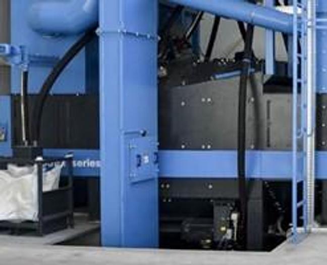
Bucket elevator
The bucket elevator is installed at the side of the machine and is used to elevate the abrasive vertically to a separator. It is operated in the sub-pressure regime and is ventilated. It is manufactured very robust and features a single length of steel, folded on CNC press brakes to ensure absolute vertical alignment.
The bucket elevator’s head section accommodates a pulley which is driven by a motor- reducer. A set of take-up plates at the head section serve to maintain elevator belt tension.
The bucket elevator’s boot section pulley has a sensor of rotation.
In case of an emergency stop of the elevator, which may well occur when the elevator’s belt is under- tensioned, the control system prevents overloading and failure of the screw conveyors. In the event of stoppage, all components used in the recirculating process are automatically switched off.
The bucket elevator shafts are mounted on dust-tight bearings. The elevator’s belt is made from a reinforced transportation belt highly resistant to abrasion. Pressed steel buckets are fastened to the belt with special concave head bolts and oval backed washers to ensure even distribution of load to ensure they do not protrude through the rubber belt onto which they are attached. They are very easy to replace and need no special tooling.
The motor reducer is protected by a motor safety relay and is provided with a brake to prevent reverse motion of the belt.
Bucket elevator motor: 1 x 4HP
Abrasive Cleaning and Storage hopper
The Bucket Elevator discharges the abrasive to the Separator where the large impurities are retained on a screen-mesh (and disposed to a trash bin) and the abrasive is cleaned by the use of an air- operated dynamic cascade system. The abrasive to be reused is cleaned very carefully and thoroughly.
The clean abrasive fills a storage hopper from which the abrasive is supplied to the turbines. The supply of the abrasive to the turbines is controlled by adjustable shut-off gate valves.
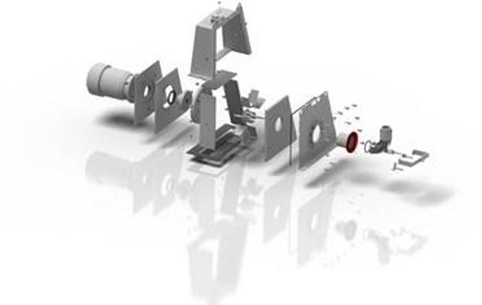
TURBINES
The turbines are located on the blast cabinet and set
at an optimum angle to blast shot directly at all the surfaces of the material to be blasted.
The AH 350 turbine is of a time-proven design and has an exceptionally long service life. The housing of the turbine body is made of hot-bent manganese
steel plates. On the inside of the housing are replaceable protective liners made of hardened steel and manganese steel from 5/16” to 3/4″ thick.
Alternative brand turbines may be supplied on the machine (subject to approval)
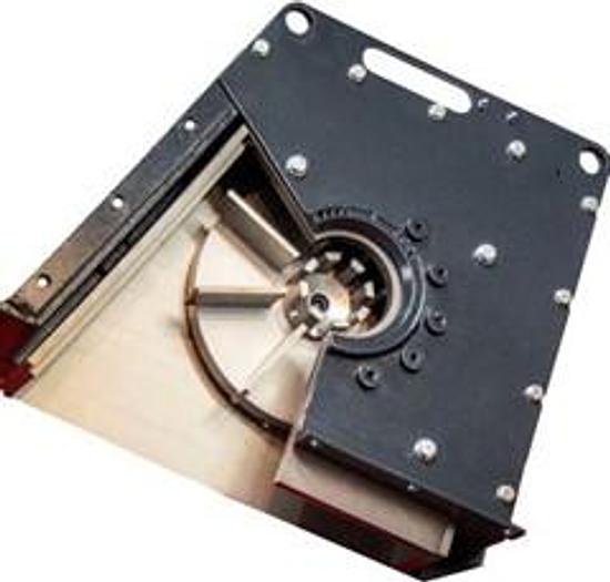
AH 350 turbines are provided with blades which are fixed to the one-sided bare wheel. The blades and the bare wheel are made of a hardened tool steel.
The impeller and control cage are also made of a hardened tool steel.
The feed spout of a turbine is made of carbon steel, but the internal surface of the elbow is additionally carburized.
The abrasive blast pattern can be easy adjusted and set from the outside.
The turbine’s parts are easily accessible from
the outside with no necessity to dismantle the whole turbine.
VENTILATION
Discharged air is subject to the 2nd stage of filtration in a caisson featuring fine filters made of polyester non-woven fabric. The unique design of the caisson also ensures noise reduction.
Deducting rate: < 2 mg/m3
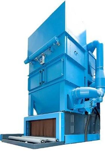
Dust Collector
The dust collector features a large separation chamber with enhanced filtration area and an air jet pulse for improved dust shake off from the filter cartridges.
The electronic control system monitors pressure drops on the filtration cartridges and thus ensures a more thorough filtration as well as extended life of the cartridges.
The suction pipe installed underneath the housing of the fan is routed to the initial separation chamber mounted on the Dust Collector. Inside the chamber, the
air stream slows down and by the same token its carrying capacity is reduced to such a degree that large contaminant particles fall directly into a waste container. Only the remaining fine contaminant particles settle on the filter cartridges. As a result, the workload for the filter is extremely low and yet a very high degree of separation is attained.
Filter cartridges are cleaned alternately.
The Dust Collector hopper features a screw conveyor For the automatic transportation of dust to the Mini Bag located on the side of the machine.
The waste bag has attached handles for easier transport by a forklift.
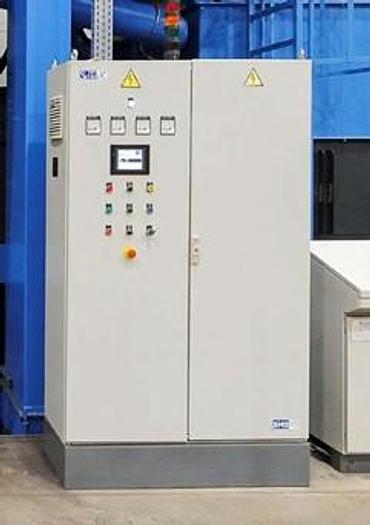
ELECTRICAL CONTROLS
All machine subassemblies are electrically controlled in a central control panel. Only standardized control
panels are used, provided with a forced ventilation system. The driving motors are protected by automatic switch-off elements and safety relays. The sub-assemblies are manufactured to the safety classes corresponding to their application types.
The control panels are manufactured to meet the most demanding criteria with regards to component selection, professional cable network, designation of cables and power connections.
All electrical components are Siemens or other recognized brand name manufacturers. All control panels are submitted to individual control tests.
The software provided is universal and enables the machine to be configured in terms of both hardware and functional operations. The control system is provided with advanced safety, operation, diagnostics and maintenance assistance functions.
Mains voltage: 400/60Hz/3Ph and 110V Control voltage: 24 V
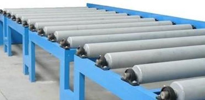
TRANSPORT SYSTEM
The material to be treated are fed into the machine by the entrance roll conveyor. The material, after blasting is completed, leave the machine on the exit conveyor.
The frames of the roller conveyors are made of steel profiles. The rolls are mounted on the frame by means of pillow block bearings. This design enables the rollers to be easily maintained.
The rollers are made of heavy wall pipes finished with welded-in shafts, one passive and the other active, on which sprockets are mounted to enable the driving force to be transmitted. All the rollers are connected with a chain. The sprockets and the chain are protected by a safety covers.
The conveyor’s drive is reversible, provided with a smooth variable speed control system.
It is driven by a motor reducer and chain and sprockets between the rolls; the protective covers are easy to dismantle and are located according to the approval drawing.
SPECIFICATIONS AND CONDITION ARE CORRECT TO THE BEST OF OUR KNOWLEDGE AND ARE SUBJECT TO YOUR VERIFICATION AND CORRECTION. THE CONDITION OF THE MACHINE IS AS IT HAS BEEN REPRESENTED TO US. ALL MACHINES ARE SUBJECT TO PRIOR SALE. EVERY MACHINE, UNLESS OTHERWISE SPECIFIED, IS OFFERED SUBJECT TO OUR GUARANTEE THAT IF FOUND TO BE MECHANICALLY UNSATISFACTORY WITHIN 30 DAYS AFTER SHIPMENT, SAME MY BE RETURNED, FREIGHT PREPAID FOR FULL CREDIT OR REPAIRED AT DEALER’S OPTION. ALL MACHINES RETURNED TO US MUST BE IN AS GOOD A CONDITION AS WHEN SHIPPED.
Specifications
| Model | CA-RS-RY 1760 |
| Condition | New |
| Material and parts to be treated | Steel plates |